Using Structurizr to Create C4 Model Diagrams
The C4 Model is a structured and hierarchical approach to visualizing software architecture. I covered the general idea in a previous post, but to summarize, there are four levels of abstraction:
- System Context: Provides a high-level overview of the software system in its environment, showing users and external systems interacting with it.
- Container: Zooms into the system, depicting the major containers (applications, services, databases) that constitute the system and their responsibilities.
- Component: Further decomposes a container into its constituent components, illustrating how the system is internally structured.
- Code: Details the internal structure of components, including classes, interfaces, or functions.
Having this tiered model allows all stakeholders to engage with the architectural diagrams depending on their level of expertise and interest.
Traditional ad-hoc architectural sketches, drawn on whiteboards or with generic drawing tools like LucidChart, Visio, or draw.io don’t enforce naming consistency or relationship correctness. In contrast, the C4 Model provides a framework for creating diagrams that are consistent and precise.
Because the C4 Model is a framework that standardizes the kinds of diagrams to create, there isn’t a formal recommendation for the tooling to use. That being said, the creator of the C4 Model, Simon Brown, also created Structurizr, a collection of tools and a domain-specific-language, to help create C4 Model diagrams.
Over the past few weeks, I’ve taken a closer look at the C4 Model by working with Structurizr to better understand the architecture of Local.
3. Structurizr: Architecture as Code
With Structurizr, you create a workspace.dsl file to contain the complete model of a software system’s elements and their relationships. From this model, multiple C4 diagram views can be generated: System Context, Container, and Component diagrams. Note that the “Code” view defined by the C4 framework isn’t included. The thinking around this is that it’s too specific and not worth keeping up-to-date within the model. Instead, if you need to visualize the code, you should try to generate it using tooling specific to the language or IDE.
One of Structurizr’s primary benefits is its “diagrams as code” approach. Because the architectural model is defined as text, changes can be tracked in version-control. Using version control allows for branch-based experimentation and collaborative editing which reduces the risk of diagrams becoming outdated or inconsistent. Diagrams can be automatically regenerated as the model is updated.
A simplified example for the Local desktop app along with Local Hub (a website to manage a user’s account) might look like:
workspace "Local" "The Local product described on https://localwp.com" {
    !identifiers hierarchical
    model {
        // Entities
        wpdev = person "WordPress Developer"
        lc = softwareSystem "Local Core"
        lh = softwareSystem "Local Hub"
        // Relationships
        wpdev -> lc "Uses"
        wpdev -> lh "Uses"
        lc -> lh "Connects to"
    }
    views {
        // https://docs.structurizr.com/dsl/language#theme
        theme default
        systemLandscape local "Local" {
            include *
            autolayout lr
        }
        systemContext lc "LocalCore" {
            include *
            autolayout lr
        }
        systemContext lh "LocalHub" {
            include *
            autolayout lr
        }
    }
}
Which can be used to generate a diagram like:
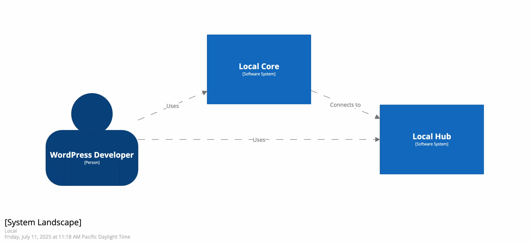
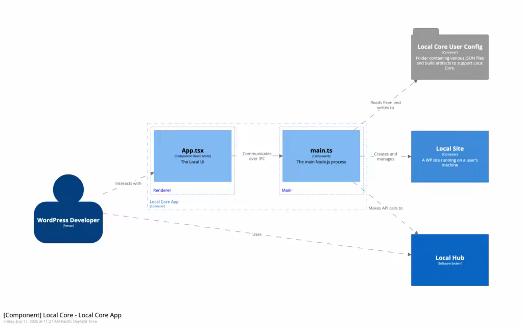
A diagram this simple isn’t useful, but by modeling more systems, containers, and components, we can get a much more useful diagram:

Structurizr’s online sandbox is a great place to try things before installing anything locally.
Getting Started Locally
The above sandbox is a decent way to try out the syntax, but eventually, you’ll want to track the model in code. I’ve found that using Structurizr Lite via a Docker container is a great way to get a feel for the language and have the resulting data saved to a file.
docker pull structurizr/lite
docker run -it --rm -p 8080:8080 -v .:/usr/local/structurizr structurizr/lite
From there, just navigate to localhost:8080 to view the compiled diagrams.
Dynamic View
One diagram that I found particularly useful recently was the dynamic view. Similar in usefulness to a sequence diagram, the dynamic view allows you to define a series of steps that are taken over time, through a system. This view shows a series of relationships between entities, an example of which might look like:
workspace "Local" "The Local product described on https://localwp.com" {
    model {
        // Define the system model ...
    }
    view {
        // Define the them and what diagrams to export  ...
        dynamic lc.app {
            title "Create a new WP site"
            wpdev -> lc.app.apptsx "Clicks the 'Add site' button"

            lc.app.apptsx -> lc.app.maints "Calls addSite() via IPC"
            lc.app.maints -> lc.config "Saves site metadata"
            lc.app.maints -> lc.ls "Provisions services"
            lc.app.maints -> lc.app.apptsx "Notifies UI via IPC"
        }
    }
}
From there, you can compile and step through the flow to get a better idea of how and when various components interact with each other: